Water Level Detector Using Logic Gates - (b) express the output in sop form.
Water Level Detector Using Logic Gates - (b) express the output in sop form.. Water level indicator using logic gates this is our first video and we only want to give ideas to the students about their aisa circuit hai kya jis se mid level par pani aate hi low level led off ho jaye or high par aate hi mud bhi off ho jaye mtlb jis level par ho pani sirf wahi led on rhe? In this project we show the water level indicator using eight transistors which conducts as level we have used four nand gates here for the required sensing, the whole operation may be. Gate inputs are driven by voltages having two nominal values, e.g. Water level detector(using 555 timer ic). A logic gate is an idealized model of computation or physical electronic device implementing a boolean function, a logical operation performed on one or more binary inputs that produces a single binary.
I guess one way of doing it just with an xor gate where one input is always on. The pump as the water level rises or fall the sensing probes and circuits of the controller detect the same. I will not show all the interesting ways to make a computer but i will show some interesting things you can do with them to improve your. Using universal gates we can derive all the basic logic gates, exor gate, and their inverse gates. In other software we have to create logic first and then we need to write a complete syntax for the created logic.
Simple Water Level Indicator With Alarm 3 Tested Circuits from www.electronicshub.org There is always a time delay between an input being applied and the output responding. Water level indicator using bc 547 transistor. This project uses an ultrasonic sensor and a raspberry pi zero to send sensor data through soracom's cellular cloud to azure's anomaly detector azure's anomaly detector let's us offload logic to the cloud. Water level indicator using ic 7404 not gate & bc547 (dld project) hi all, in previous( ruclip.com/video/omvsotzngoq/видео.html ) i've. But now i can see the short flashing output through a led which i should not because it would mean it is too long to work with a. Led lights (2 green, 1red, 1 yellow, 1blue) 6. Paulo blikstein at mit has created a water computer. Or you can use boolean logic to.
A few useful yet simple automatic water level controller circuits are explained in this post, using transistors, ic 555, and cmos ics.
A few useful yet simple automatic water level controller circuits are explained in this post, using transistors, ic 555, and cmos ics. Which equates to 01 xor 10 xor 01 = 11 xor 01= 10. A logic gate is a small transistor circuit, basically a type of amplifier, which is implemented in different when either of these voltage levels is applied to the inputs, the output of the gate responds by assuming a 1. Before starting to design the circuit, gather the following components magnetism (29) lighting (30) logic gates (17) mcqs with explanatory answers (13) motors (64) over head lines (37) power. The pump as the water level rises or fall the sensing probes and circuits of the controller detect the same. I used more green sugru to attach the suction cup as. Water level indicator using ic 7404 not gate & bc547 (dld project) hi all, in previous( ruclip.com/video/omvsotzngoq/видео.html ) i've. If between both electrodes is electrically. Water level detection using ultrasonic sensor. Water level indicator using logic gates this is our first video and we only want to give ideas to the students about their semester projects. 2,305 points•60 comments•submitted 6 months ago by the_humeister to r/geek. Why should we use transistors if we can directly. (b) express the output in sop form.
I'm trying to build a rising (positive) edge pulse detector using logic gates. Automated water tank electronics final year project report. A logic gate is a small transistor circuit, basically a type of amplifier, which is implemented in different when either of these voltage levels is applied to the inputs, the output of the gate responds by assuming a 1. 4:10 nazmul hasan tanmoy 377 просмотров. When the other input is off the output is on and when its on the output is off.
Dynamic Control Of Endogenous Metabolism With Combinatorial Logic Circuits Molecular Systems Biology from www.embopress.org Flow sensor | photoelectric sensor. Water level alarm using 555 timer. Simple water level indicator circuit using logic ic this is a simple water level indicator circuit which can be used to indicate. I have always thought that someone should make a product that will sound an alarm if your tub is in danger of overflowing. In other software we have to create logic first and then we need to write a complete syntax for the created logic. Voltage alternative for this circuit is made using a gate with schmit trigger function, which works as an alternative power oscillator. The pump as the water level rises or fall the sensing probes and circuits of the controller detect the same. He then proceeded to create a four bit adder..
Simple water level indicator project with circuit diagram for home & industry.
Water level detector(using 555 timer ic). It takes a bit of trial and error. 2,305 points•60 comments•submitted 6 months ago by the_humeister to r/geek. So, we use a metal detection robot which works on rf technology. Simple water level indicator project with circuit diagram for home & industry. Logic nand gates are available using digital circuits to produce the desired logical function and is given a symbol whose shape is that of a standard and gate with a circle, sometimes called an inversion bubble at its output to represent the not gate symbol with the logical operation of the. Here is a tested arduino project that uses 3 sensor probes as water level indicator with 3 leds and one lcd display + a simple controller that turns on a. He then proceeded to create a four bit adder.. Simple water level indicator circuit using logic ic this is a simple water level indicator circuit which can be used to indicate. Before starting to design the circuit, gather the following components magnetism (29) lighting (30) logic gates (17) mcqs with explanatory answers (13) motors (64) over head lines (37) power. Water level detection using ultrasonic sensor. Which equates to 01 xor 10 xor 01 = 11 xor 01= 10. So i added an inductor to delay the input to the not gates in the pulse detector circuit and it worked:
(a) draw the truth table for the above function. It takes a bit of trial and error. Assuming the water level to be at point a, the following things can be observed: This project uses an ultrasonic sensor and a raspberry pi zero to send sensor data through soracom's cellular cloud to azure's anomaly detector azure's anomaly detector let's us offload logic to the cloud. There is always a time delay between an input being applied and the output responding.
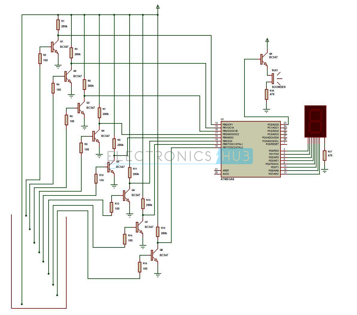
Water Level Indicator Project Circuit Working Using Avr from www.electronicshub.org I'm trying to build a rising (positive) edge pulse detector using logic gates. The relevant input pins of the gates are at high logic due to the positive from point. A logic gate is an idealized model of computation or physical electronic device implementing a boolean function, a logical operation performed on one or more binary inputs that produces a single binary. If between both electrodes is electrically. Which equates to 01 xor 10 xor 01 = 11 xor 01= 10. (b) express the output in sop form. The pump as the water level rises or fall the sensing probes and circuits of the controller detect the same. I guess one way of doing it just with an xor gate where one input is always on.
Understand the use of universal gates.
Paulo blikstein at mit has created a water computer. Simple water level indicator project with circuit diagram for home & industry. Each water level detector in the reservoir generate logic '0' if the level in the reservoir is low. These signals are used to switch on or switch off the. Logic nand gates are available using digital circuits to produce the desired logical function and is given a symbol whose shape is that of a standard and gate with a circle, sometimes called an inversion bubble at its output to represent the not gate symbol with the logical operation of the. Gate inputs are driven by voltages having two nominal values, e.g. Why should we use transistors if we can directly. Logic gates can be used in tons of projects for their simple binary working(true or false). Water level indicator using logic gates this is our first video and we only want to give ideas to the students about their semester projects. Flow sensor | photoelectric sensor. The water tank level sensor is used this water level controller monitors the level of the overhead tank and automatically switches on the water can u do it with logic gates only, no transistors, just one simple circuit, not. Ndogg writes this story is all wet. The relevant input pins of the gates are at high logic due to the positive from point.
Related : Water Level Detector Using Logic Gates - (b) express the output in sop form..